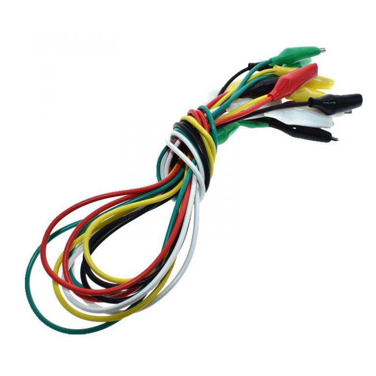


Covered test points (Solder mask to be removed to access test point).This page discusses the micro:bit schematic and Bill of Materials BOM, which shows the electrical connections of the micro:bit and the components used in it. The micro:bit V1.3 and V1.5 schematic is available from the BBC’s micro:bit hardware repository. Manufactured using optimum grade mild steel, these clips are insulated from the side and wire cab be connected by the screw, soldering or accepts one mm plug. The micro:bit V2 schematic is available from the Micro:bit Educational Foundation microbit-v2-hardware repository. We are one of the leading organizations engaged in manufacturing and supplying superior quality Thumb type Crocodile Clip. If you’re looking to make something of your own based on the micro:bit, you might prefer to use our ‘Reference Design’ which is based on a radio module and has space on the layout for you to add your own components. Schematicsīelow is the pinmap and allocation of the nRF52833, more information is available on the micro:bit V2 schematic GPIO on nRF52833īelow, we’ve extracted some useful details about the hardware that anyone implementing software for the micro:bit, interfacing to it, or designing an add-on board for it should find useful. The LED matrix is physically laid out as a 5x5. On the V2 board this is implemented as a 5x5 matrix, but in the V1, this is implemented as a scanned matrix of 9x3 (i.e. Row 2 Col 8, and Row 2 Col 9 are not used. The LED matrix is driven via a high-speed multiplex generated by application processor software. This software also uses the LED Row and Col pins to implement the light sensing feature, as such you may see a difference in sensitivity between board revisions. Some of the Columns appear on the edge connector, so if you want to use extra GPIO pins, you have to disable the display in software.


 0 kommentar(er)
